






















The use case determines the starting brief
Tensile Walkway Structure in Nainital, Uttarakhand
Nainital · Tensile Walkway Structure
Tensile Walkway Structure in Nainital
Below, see real project photography, current starting pricing, and how we take a Tensile Walkway Structure in Nainital from enquiry to handover.

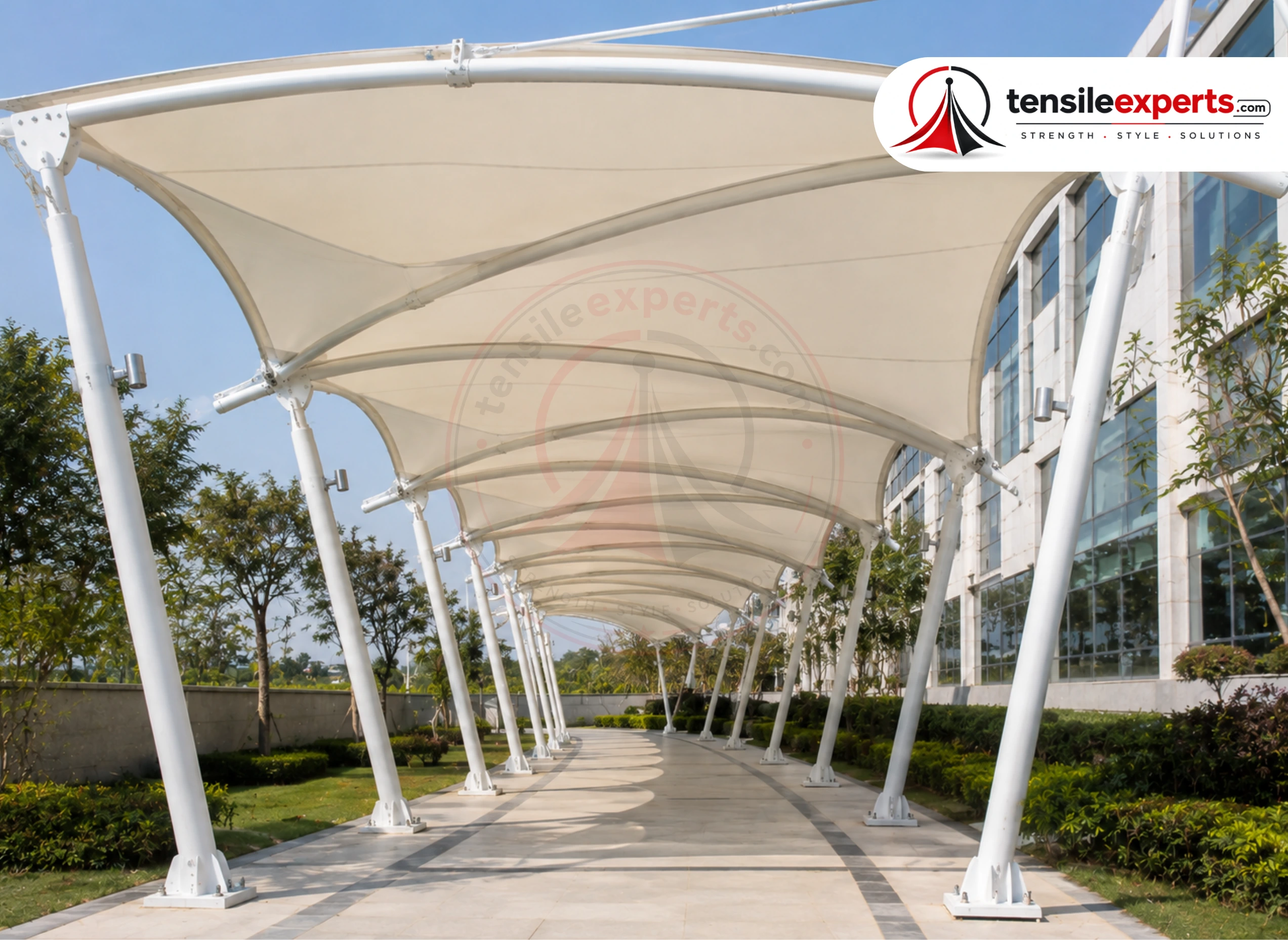
From ₹350/sq.ft.
Indicative starting price. Final pricing depends on size, design, fabric, structure, foundation, installation and site conditions.
Available for Custom Projects
Starting price · Updated Aug 2026
 Real project imagery
 In-house project delivery
Follow the route geometry without losing clear, dry movement.
A Nainital walkway may need to respond to gradients, ramps, steps, retaining edges, sharp bends, exposed gaps, downhill runoff, limited delivery sizes, and staged erection along a constrained route.
Regional context guides what the survey checks first
Dimensions and supports checked before fabrication
Topography can influence wind exposure, accessible gradients, support levels, footing positions, runoff, transport, and temporary stability. Site geometry is required before the repeated module is fixed.
Application fit
Where a Tensile Walkway Structure can fit in Nainital.
Campus links, hospital routes, industrial circulation, and hospitality walkways carry different users and services, so route continuity and interruption points matter more than one typical bay.
Campus and institutional links
Connect blocks around class or shift peaks, accessible movement, crossings, landscaping, wayfinding, lights, CCTV, and repeated supports without narrowing the route.
Planning point 01Hospitals and care circulation
Maintain clear movement for wheelchairs, stretchers, attendants, trolleys, and emergency interfaces while managing slopes, doors, lighting, drainage, and dry handovers.
Planning point 02Industrial and operational routes
Separate pedestrians from vehicles or plant while coordinating gates, services, fire access, shift traffic, clear height, impact risk, drainage, and phased installation.
Planning point 03Hotels, resorts, and public venues
Link arrivals, rooms, amenities, or event areas with useful shade and rain cover while respecting landscape, guest movement, route changes, lighting, and visual continuity.
Planning point 04
Route layout comparison
Which walkway system fits the route and its interruptions?
One standard module rarely solves the whole path. Clear width, direction changes, support exclusions, crossings, building tie-ins, drainage zones, and expansion or erection breaks decide how the route is divided.
| Structure type | Support or operating logic | Often considered for | Confirm before choosing |
|---|---|---|---|
| 01Single-edge cantilever route | Supports kept mainly along one boundary or controlled edge | Narrow paths, building edges, and routes where the main pedestrian side should remain open | Projection and uplift, footing or wall capacity, clear width, door and ramp conflicts, low edges, impact protection, and discharge direction. |
| 02Two-edge modular walkway | Repeated supports on both sides of a defined pedestrian corridor | Long campus, hospital, housing, and industrial links where a consistent clear corridor can be maintained | Support rhythm, accessible width, bay joints, crossings, services, lighting, repeated outlets, expansion breaks, and foundation positions. |
| 03Independent spine or alternating supports | Central or alternating supports used to respond to bends and edge restrictions | Landscaped paths, wider circulation zones, and routes where utilities or entrances prevent a regular two-edge grid | Pedestrian separation, headroom, membrane drainage, branch connections, sight lines, column protection, underground services, and erection sequence. |
Visual reference
Compare form, frame and finished coverage.
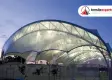
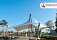
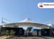
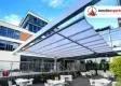
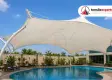
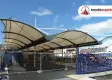
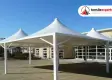
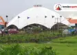
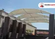
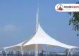
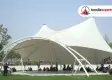
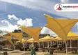
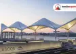
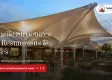
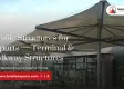
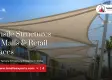
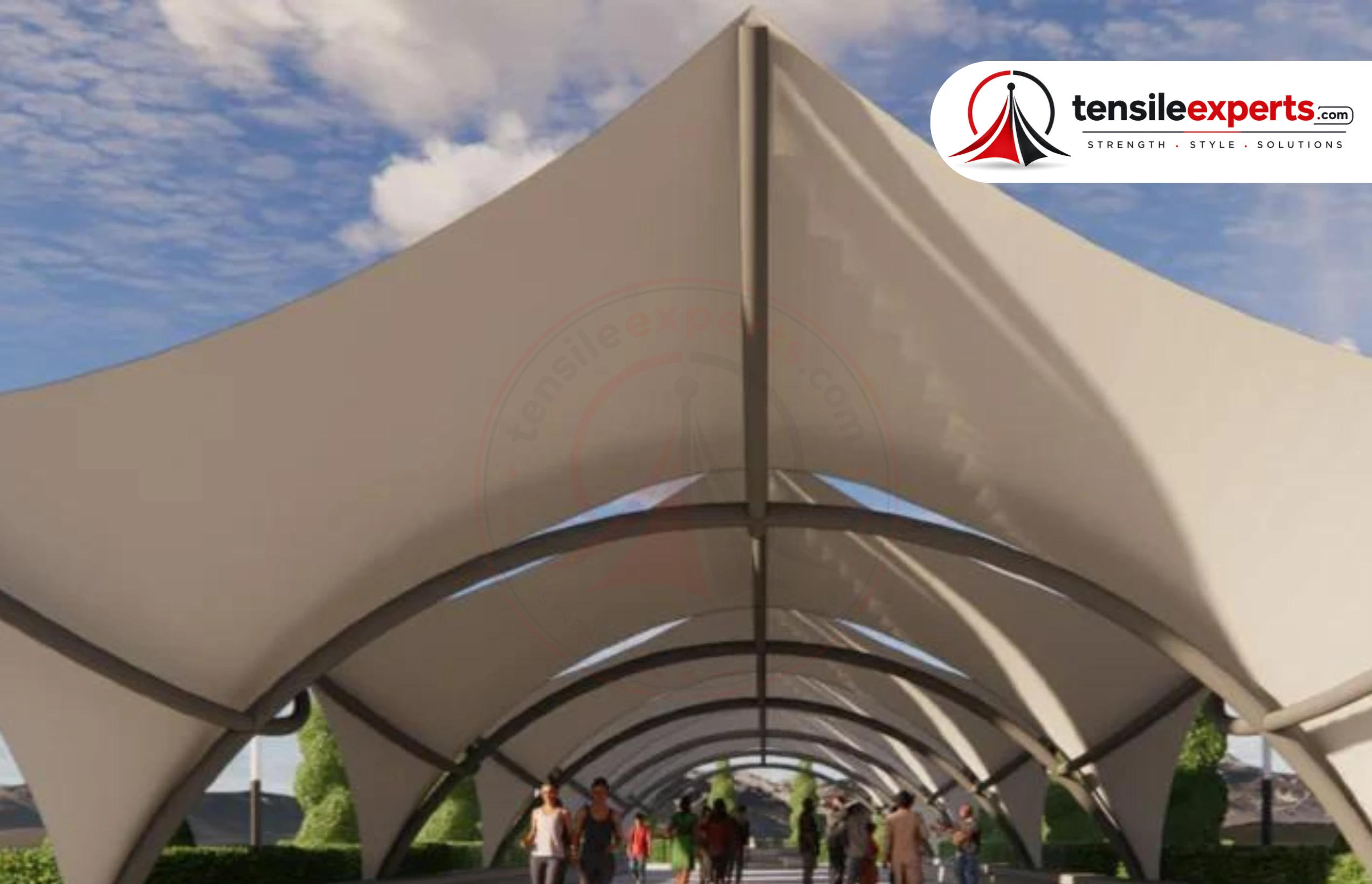
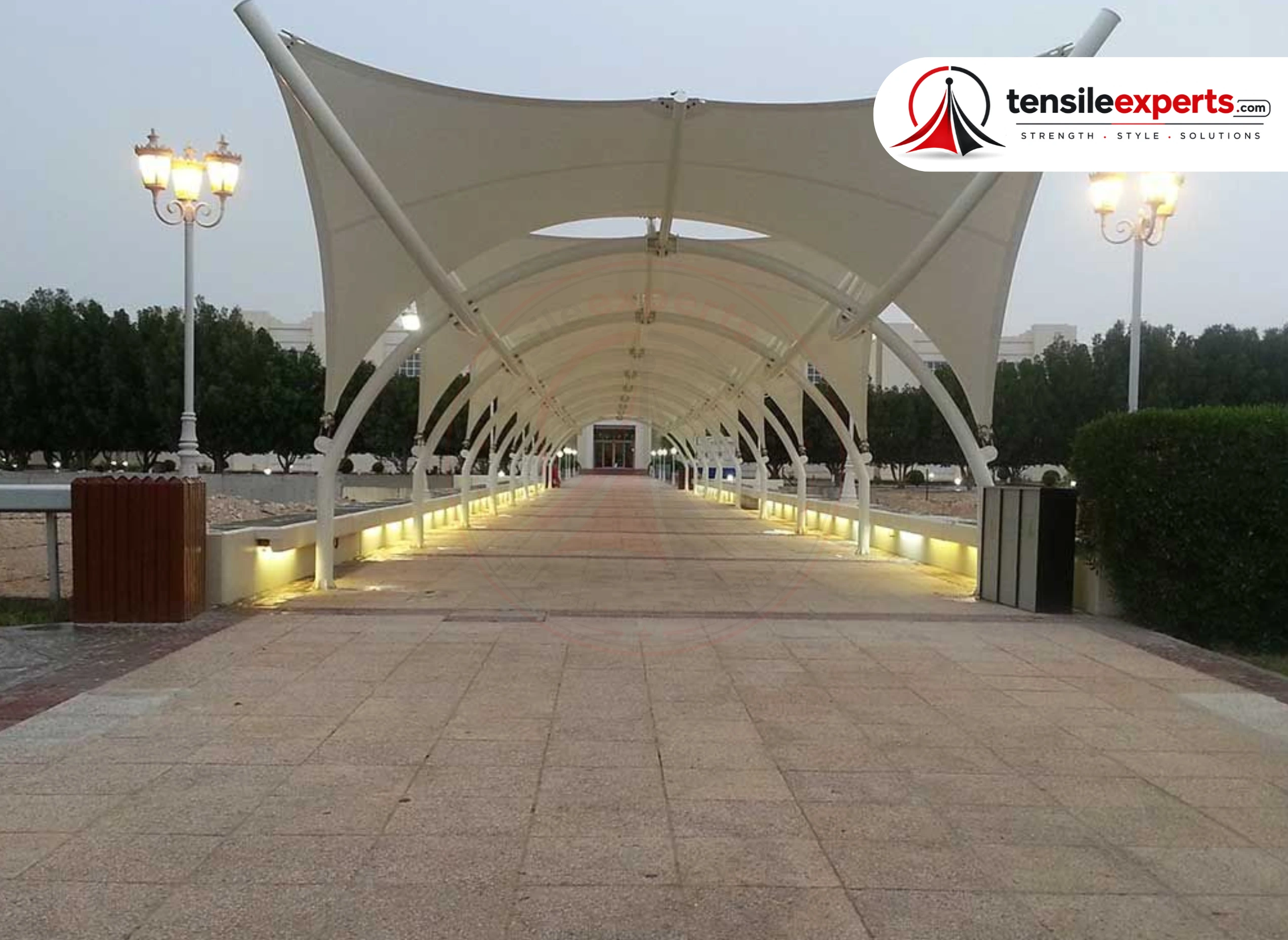
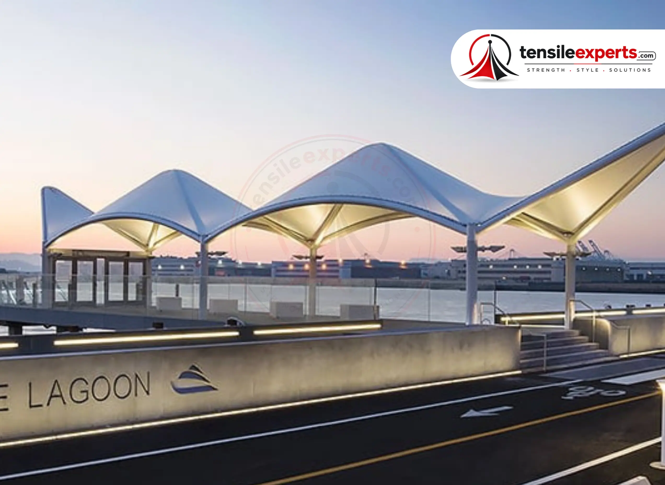
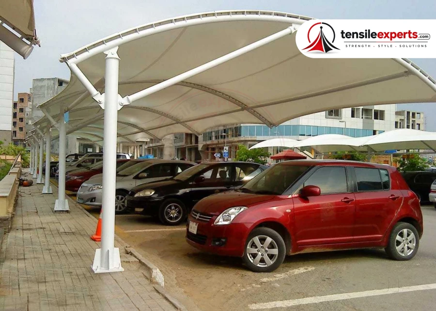
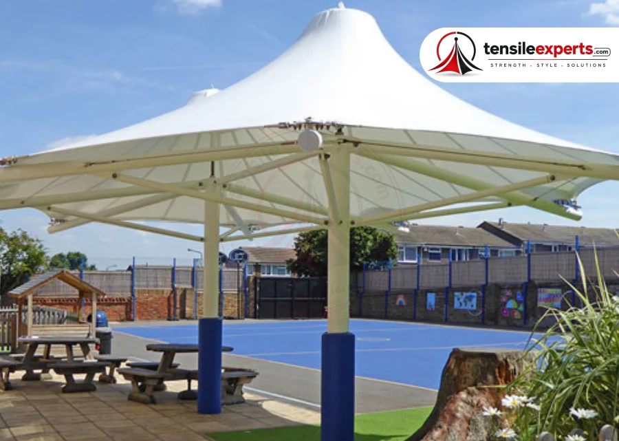
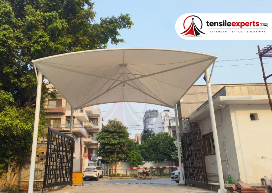
Use the photographs to discuss geometry and workmanship. They are product references, not claims that every photograph was completed in Nainital.
Before design approval
Four checks that should shape the concept.
Topography can influence wind exposure, accessible gradients, support levels, footing positions, runoff, transport, and temporary stability. Site geometry is required before the repeated module is fixed.
Longitudinal levels and accessible movement
Record gradients, landings, ramps, steps, retaining construction, bends, widths, crossfalls, exposed edges, entrances, and downhill drainage.
What clear width and height are required for pedestrians, wheelchairs, stretchers, trolleys, cycles, or occasional service vehicles?
Resolve the answer against measured dimensions, the occupied area, required clearances, support conditions, and the approved structural concept.
Where do route bends, crossings, doors, ramps, stairs, trees, services, fire access, and building joints interrupt the support rhythm?
Nainital receives about 2305.3 mm of annual rainfall across roughly 87.2 rainy days (IMD 1961-1990 normals), which we factor into drainage and material planning for every Tensile Walkway Structure here.
Segmented delivery and erection
Confirm access width, component lengths, unloading points, lifting or scaffold zones, temporary route diversions, weather limits, and a stable bay-by-bay sequence.
Technical schedule
Project values to confirm before fabrication.
The design schedule should connect the Nainital site basis to the continuous pedestrian cover, accessible clear width, repeated bays and coordinated drainage, not present one unsupported wind-resistance claim.
| Design parameter | Unit or project record | What should be confirmed |
|---|---|---|
| 01Product geometry and span | Linear — 10m–100m+ length, 2m–4m width per bay | Verify the measured footprint, governing span, edge positions, usable area, and permitted support locations. |
| 02Clear height and interfaces | 2.5m–4m | Record required clearances plus doors, vehicles, lights, services, signage, equipment, and maintenance access where applicable. |
| 03Continuous route and clearance | Chainage plan/sections | Record route centreline, bends, widths, heights, slopes, ramps, crossings, doors, accessibility, support exclusions, tie-ins, and dry handovers. |
| 04Repeated bay and joint logic | Bay/interface schedule | Set support spacing, module changes, movement joints, building interfaces, low points, lights, CCTV, signs, services, and erection breaks. |
| 05Route-wide drainage | Outlet/discharge schedule | Coordinate high and low points, outlet spacing and capacity, overflow, splash control, downpipes, downstream discharge, blockage access, and ponding checks across all bays. |
| 06Route safety, lighting, and phased installation | Operations and method plan | Coordinate accessible and emergency movement, crossings and doors, lighting and CCTV, signs and services, temporary pedestrian diversions, delivery and erection bays, public protection, inspections, and maintenance access. |
| 07Basic and design wind speed | m/s or km/h | Record the site wind-speed basis and the factors applied for risk, terrain, height, and topography under IS 875 (Part 3):2015. |
| 08Design wind pressure | kN/m² | State the calculated pressure and suction cases, including the external and internal pressure coefficients used for the actual membrane form. |
| 09Membrane and form-finding | PVC or PTFE depending on length and exposure | Confirm structural form, membrane grade, warp and weft pre-stress, seam pattern, edge details, light transmission, finish, and certification requirements. |
| 10Steel, anchors and foundations | Footings spaced along the full walkway route, not just at the ends | Connect member sizes, connections, base plates, anchors, footings, protection system, and existing-support checks to the governing reactions. |
| 11Drainage and ponding review | Falls and outlet capacity | Document high and low points, runoff paths, outlets, discharge locations, loaded membrane shape, blockage risk, and maintenance access. |
Indicative product ranges are planning references, not project calculations. Final values depend on geometry, height, exposure, supports, use, and verified site inputs.
BIS wind-load reference
Project delivery · North India
One accountable route from requirement to handover.
Chainage survey, accessibility and movement checks, support and foundation verification, repeated membrane and steel design, joints, services, route-wide drainage, fabrication tolerances, temporary circulation, phased erection, tensioning, and handover are coordinated as one walkway system.
-
01
Share the complete route
Send a marked plan, dimensions and levels, route users, required width and height, bends, crossings, doors, ramps, photographs, services, and drainage information.
-
02
Survey chainage and interfaces
Verify clear corridor, support exclusions, utilities, building tie-ins, levels, accessibility, outlet routes, delivery points, temporary circulation, and erection access.
-
03
Engineer the repeated system
Finalize modules and transitions, membrane, steel, connections, foundations, joints, clearances, lights or CCTV interfaces, drainage, drawings, and installation sequence.
-
04
Fabricate and install in stages
Coordinate bay-marked fabrication, transport, route protection or diversions, sequential erection, membrane tensioning, drainage checks, inspection, and sectional handover.
Service coverage
Tensile Walkway Structure planning in Nainital and across Uttarakhand.
Route gradients, access, topographic survey, transport sizes, runoff, and segmented installation are confirmed for the individual Nainital site.
Need the complete product overview, membrane options, specifications, and pricing context?
Covered walkway structures connecting buildings, parking areas, and campus paths.
Open product guide
Covered walkway structures connecting buildings, parking areas, and campus paths.
Site conditions in Nainital shape our approach as much as the brief does. Nainital sits at about 2,084 m elevation in a mountain valley in the Kumaon foothills of the outer Himalayas, centred on the eye-shaped Nainital Lake (1,940 m, 1,433 m long, 463 m wide), with Naina Peak the highest point nearby at 2,619 m. That's the starting point for every Tensile Walkway Structure we design here.
Walkway structures are usually a long, narrow span — anchoring points are planned along the full route, not just at the ends. Share your project details and we will confirm a realistic timeline.
Commonly used for Covered walkways connecting buildings, parking areas, or campus paths, Pedestrian routes needing weather protection.
Why Tensile Experts
Why Nainital Clients Choose Tensile Experts
Site Assessment Before Fabrication
On a Tensile Walkway Structure project, most avoidable issues come from skipping a proper site assessment or choosing the wrong fabric grade for the climate — we check both before fabrication.
We Know Nainital's Conditions
Nainital sits at about 2,084 m in a Himalayan mountain valley around a lake, with very heavy rainfall for a hill town. A useful first review confirms site access, slope, and drainage — none of which can be assumed from a plains profile.
Realistic Timeline Guidance
Walkway structures are usually a long, narrow span — anchoring points are planned along the full route, not just at the ends. Share your project details and we will confirm a realistic timeline.
In-House Fabrication & Installation
From design to installation, your project is handled by our own team — not outsourced to a third-party crew.
See our manufacturer profile for Nainital for our full range and service capabilities there.




Project Experiences
Built spaces. Shared experiences.
See the structure, understand the brief, and hear how the project experience felt from the client side.
Client feedback
0105
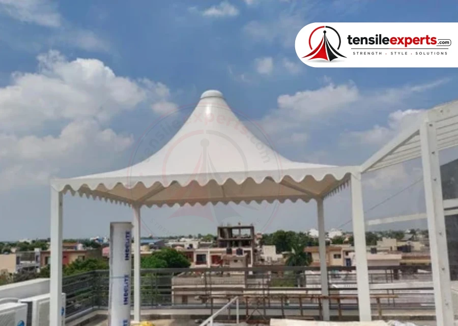
Parking shed ka work really good tha. Size aur design hamari parking space ke according suggest kiya aur final finishing bhi neat hai. Overall very satisfied.
Really liked the gazebo they made for our outdoor area. Simple design but looks very premium after installation. Team was responsive throughout the work.
We needed a tensile canopy for our office entrance. They suggested a design that matched the building quite well. Installation was smooth and the final structure looks professional.
Very happy with our terrace pergola. Exactly the kind of covered sitting space we were looking for. Good workmanship.
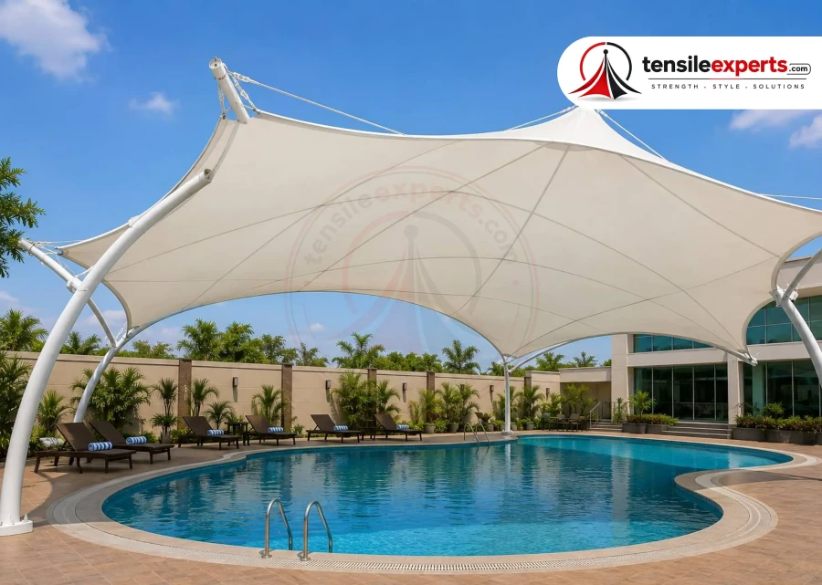
Swimming pool shade came out better than expected. Main concern was getting enough shade without covering the whole pool area, and the design worked perfectly for that. Nice work.
Frequently Asked Questions
Tensile Walkway Structure FAQ — Nainital Projects
Direct answers to the most common questions about Tensile Walkway Structure fabrication, materials, and installation for projects in Nainital.
Tensile Walkway Structure — Common Questions
1 Do you design and install Tensile Walkway Structure projects in Nainital?
Yes. Tensile Experts coordinates site review, custom design, fabrication, transport planning, installation, tensioning, and handover for Tensile Walkway Structure enquiries in Nainital. Final scope depends on the measured site and approved design.
Record gradients, landings, ramps, steps, retaining construction, bends, widths, crossfalls, exposed edges, entrances, and downhill drainage. The survey also verifies exposure, support conditions, levels, access, drainage, utilities, and erection space.
The measured route must coordinate gradients, landings, ramps and steps, retaining conditions, exposed edges, support levels, downhill runoff, delivery limits, and bay-by-bay erection. Structural and foundation requirements follow the actual topography.
PVC — suits shorter walkways with moderate exposure PTFE — recommended for longer walkways or higher exposure The final recommendation is recorded for the actual project rather than selected from the city or product name alone.
A final value cannot be chosen from the city name or a generic product brochure. The engineer establishes the wind-speed basis and calculates pressure, suction, membrane stress, member forces, anchor reactions, and foundations for the terrain, height, topography, permeability, geometry, and actual supports.
Send the exact site address, dimensioned plan or clear measurements, photographs from several angles, intended use, required clearance, preferred design direction, existing drawings, access restrictions, utilities, surrounding levels, and the available rainwater discharge route.
Chainage survey, accessibility and movement checks, support and foundation verification, repeated membrane and steel design, joints, services, route-wide drainage, fabrication tolerances, temporary circulation, phased erection, tensioning, and handover are coordinated as one walkway system.
Key Terms — Tensile Structures
Plain-language definitions for the materials and engineering terms you will hear while planning a project.
01
Retractable Structure
A tensile roof that can be opened or closed on demand, motorized or manual, for spaces that need sun cover one moment and open sky the next.
02
Anchoring
The foundation and hardware system that holds a tensile structure's cables/frame in place — critical to how the structure performs in wind and rain.
03
Span
The distance a tensile structure covers without intermediate support — larger spans need higher-grade fabric and stronger anchoring.
04
Structural Form
The overall shape the membrane is tensioned into — conical, dome, saddle, barrel-vault, or a custom form — chosen for the site, span, and drainage needs.
05
Tensile Structure
A structure that gets its strength from fabric held in tension between rigid supports, rather than from a solid roof — lightweight, weatherproof, and suited to large spans.
06
PVC Fabric
PVC-coated polyester fabric — the most widely used and cost-effective tensile membrane material for most structures.
07
PTFE Fabric
PTFE (Teflon-coated) fabric — higher UV and weather resistance with a longer service life, suited to larger spans.
08
PVDF Fabric
A durable, self-cleaning fabric top-coat option that holds its appearance longer in dusty or high-pollution environments.
09
Membrane Structure
A tensile structure formed from a single continuous fabric membrane stretched over a supporting frame or cables.
 Delhi · Pan-India execution
Project consultation
Build the right tensile structure for Nainital.
Send us your application, approximate size and site location. We’ll help you identify the right structural approach and membrane option.
01 Share your site
02 Review the concept
03 Plan execution